Modeling Clouds for Large Area Collects (Under Development)

We often want the ability to add clouds to a large scale scene in order to see the reflective, transmissive and shadowing effects on the scene. In these cases we are not so much concerned with the absolute radiometry of the clouds (true multiple scattering, exact modeling of limb regions, etc..), as we are with capturing bulk effects (single-scattering contributions, transmission effects, realistic spatial distributions, etc..).

With these cases in mind, and to support modeling of the next generation Landsat sensor, we are developing a simplistic and very fast large-scale cloud model based on using the USAF Cloud Scene Simulation Model (CSSM) and OPAC data to generate voxelized representations of inherent optical properties. DIRSIG uses this data to drive a simple radiative transfer model that captures the bulk of the radiometric effects on the scene with very little additional computation overhead. The process is currently going through a period of validation and refinement and should be available to the general user in the near future.
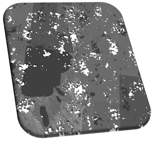
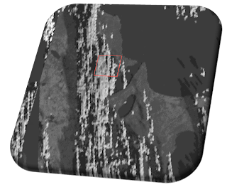
The two images shown are prototype (single wavelength) visualizations demonstrating thin, cirrus-like clouds (right) and thick, cumulus-like clouds (left). Both images show a large collect over Lake Tahoe (note that only part of the scene is available at this time, the rest is filled in with generic background materials), the cirrus demo is a zoomed in portion of the same scene. The apparent "jaggedness" of the images is an artifact of the particular sensor being modeled and is an intended effect. In both cases, CSSM was used to generate semi-random (wind-vector based) 50km x 50km x 10km volumetric concentration maps which give the spatial distributions seen.

Comments

Popular posts from this blog

LIDAR Point Cloud Visualization

A common question we get asked is how to visualize the point cloud data produced by either the Linear-mode or Geiger-mode LIDAR simulations. First, you should remember that the point cloud files produced by the "APD Processor" are simple ASCII/text files. Each line is the entry for a single return or "point" in the point cloud, including the point location and some attributes that vary depending on whether you modeled a Linear-mode or Geiger-mode system. For a Linear-mode system, a point cloud file will generally look like the example below: 12.7388 -45.3612 -0.0256 5.0290 0 0 0 0 12.8169 -45.3612 -0.0264 4.8362 0 1 0 0 12.8950 -45.3612 -0.0271 4.8362 0 2 0 0 ... 32.4008 -25.5446 10.5945 4.6783 0 65533 0 0 32.4781 -25.5446 10.5953 5.8959 0 65534 0 0 32.5360 -25.5640 12.5408 5.9185 0 65535 0 0 The first three columns are the X/Y/Z location of the point return. The 4th column is the intensity (in photons). Since Linear mode can support multiple returns per pulse, t...

Viewing and Importing DIRSIG Output Images

We are often asked what programs can view DIRSIG's image outputs and how to import the raw DIRSIG image data files into other tools for further processing. For basic image viewing, DIRSIG-4.4.0 now includes a very simple viewing tool. Launch it from the main simulation editor window by selecting the "Start image viewer" option from the "Tools" menu. If you run your simulation from the GUI simulation editor, new image files are automatically added to the list in the image viewer as they are generated. If you want to manually add files to the list, simply select the "Open" item from the "File" menu or the toolbar. Here is a screenshot of the main image viewer window. The top part contains the list of currently opened files and the bands within those image files. To view a single band as a gray-scale image, choose "Single Band Display" from the combo box and then click on the image band that you want. Finally, click "Load Band...

DIRSIG5: An introduction, a timeline and a paper

Although we will be devoting more time to this topic in the blog, many of you are aware that the next generation version of DIRSIG (aka DIRSIG5) has been under development for the past 2 years. This was a ground-up, restart from zero, etc. effort that establishes the DIRSIG modeling toolkit for the next decade. New core, new approach Although we have developed a compatibility layer to allow existing DIRSIG4 simulations to run, the DIRSIG5 model is radically different under the hood. The lightweight and highly optimized radiometry core uses a different numerical radiometry (light transport) approach than we used in DIRSIG4. In addition to being faster (less work to get an accurate answer) this algorithm is far better suited for parallelization. As a result, we have implemented micro-scale parallelization (multi-threading on multi-core CPUs) from the start and work on macro-scale parallelization (MPI distribution on cluster-style computing) is getting underway. This radiometry core al...