When we first started on the DIRSIG model in the late 1980s, 3D computer graphics was still in its infancy. At the time, standard file formats for 3D geometry were still being established. In addition, the DIRSIG model had the need for a specific set of per-facet attributes (material ID, thickness, override temperature, etc.) that are still somewhat unique in the 3D modeling community. As a result, the DIRSIG specific Geometric Database (GDB) format was created and is still used to this day.
In the mean time, a variety of 3D geometry file formats have become widely used. Although the GDB format serves our needs well, it requires the user to translate the 3D geometry assets from other formats in order to use them with DIRSIG. Lately we have been experimenting with using the Alias/Wavefront OBJ file format as a possible replacement for GDB.
The important features of the OBJ format are:
- It is widely supported by 3D geometry authoring tools (Rhino, SketchUp, Blender, etc.).
- It supports per-facet material attribution.
- It supports a single level of facet grouping (comparable to the GDB "parts" concept).
- It uses "shared vertex lists" which cut down on file size, memory usage, and precision issues that lead to gaps at vertexes and along edges.
- It supports "texture vertexes" which is a texture coordinate system tied to the object coordinate system (rather than the global coordinate system) and allows for "wrapping" material, texture, etc. maps onto/around objects.
- It supports "vertex normals" which allows an otherwise flat facet to appear to have curvature by spatially interpolating normals defined at the vertexes.
- Only "facet" constructs ("f" entries) are currently supported (not "points", "lines", "curves", etc.).
- Facets are assumed to have either 3 or 4 sides/vertexes.
- The material tag (the "usemtl" entries) is assumed to have a DIRSIG material ID associated with it.
- Texture vertexes (the "vt" entries) are read and used with any mappings applied to the geometry.
- Vertex normals (the "vn" entries) are read and automatically used to compute the normal across a facet.
- The use of "groups" (the "g" entries) is allowed and even encouraged to help users organize the components of the geometry. However, internally DIRSIG doesn't leverage them in any way.
- Shading groups (the "s" entries) are not relevant to DIRSIG since all modeling is controlled via material descriptions.
- In general, any element that DIRSIG doesn't support is simply ignored, so you don't need to filter out unsupported features in the OBJ file.
In the coming months, we will attempt to document some more details about how we have been using OBJ files in our scene construction workflow. In the meantime, check out some of the demos that are already using OBJ files. These include:
- Movement1
- UvMapping1
- VehicleGlint1
- VertexNormals1
- Water1

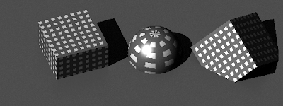
The "UvMapping1" demo employs two different objects described by OBJ files. The cube shaped object uses "texture vertexes" which is why the texture rotates with the titled cube on the right.
The "VertexNormals1" demo features a crude model of a monkey head. The version on the left is modeled with constant normals across each facet. The version on the right uses vertex normals which allows DIRSIG to interpolate the normal across each facet and create the illusion of curvature (note that the computed normal is used by all radiometric calculations).
When using OBJ instead of GDB you gain nearly seamless inter-operability with most CAD tools. In some cases those tools might preserve the material assignments, which means an OBJ can be moved back and forth without the need to re-attribute. Plus, you get support for numerous features (texture vertexes, vertex normals, smaller files, etc.) that the GDB format doesn't have. What you give up when using OBJ is the options for per-facet thickness and per-facet override temperatures. If you have not been using either of these features of the GDB format, then the OBJ format might be right for you.

Comments